Skip to content

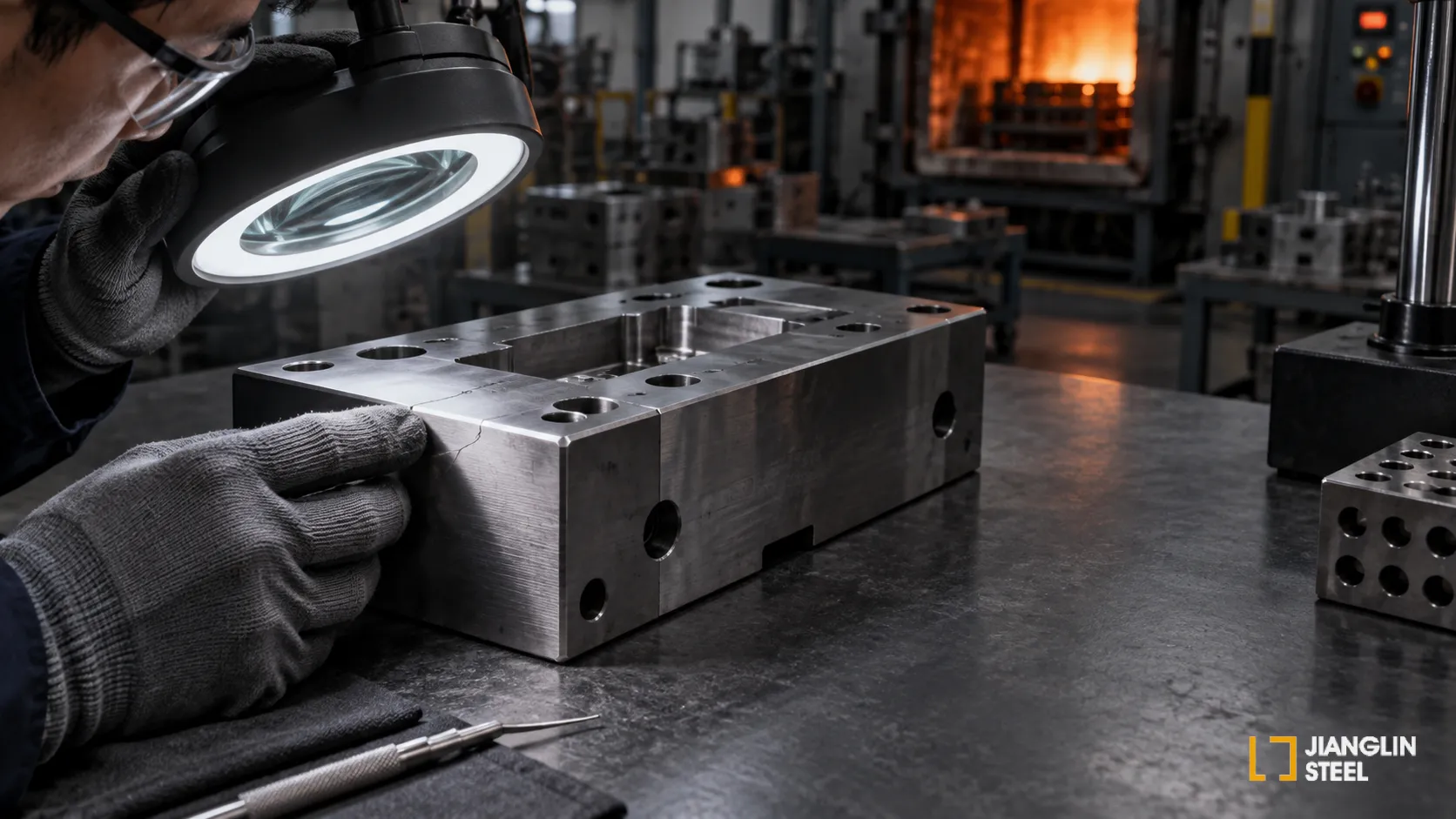
DC53 steel can leave the furnace at the expected hardness and still develop a fine crack beside a corner, hole, or EDM surface. Blaming the steel is easy, but it is often wrong.
DC53 combines high hardness with better toughness than conventional SKD11-type die steel. It is not immune to thermal stress, poor geometry, delayed tempering, or aggressive finishing. Most failures occur when several smaller risks overlap.
The useful question is not only “Why did DC53 crack?” It is: when did the crack begin, where did it begin, and which operation created the stress that opened it?
Why does DC53 steel crack?
DC53 usually cracks because temperature differences, phase-transformation stress, machining stress, and local stress concentration act together. The crack may become visible during quenching, although its origin may be an earlier machining mark, sharp internal radius, blind hole, or damaged EDM layer.
The crack’s timing provides the first clue:
| When the crack appears | Likely contributors | First checks |
|---|---|---|
| Immediately after quenching | Uneven cooling, sharp geometry, excessive thermal difference | Load position, cooling flow, radii and section changes |
| Before or during tempering | Delayed tempering or severe quench stress | Transfer time and part temperature |
| After grinding | Grinding burn or excessive stock removal | Wheel condition, coolant, feed and surface etching |
| After EDM or wire cutting | Recast layer, microcracks and tensile stress | Finishing passes and damaged-layer removal |
| During service | Earlier heat-treatment damage, excessive hardness or overload | Fracture origin, microstructure and operating load |
A crack seen after grinding is not automatically a grinding crack. The last operation may only expose damage created earlier.
Control heating before changing the steel
Daido Steel’s DC53 data gives a standard austenitizing range of 1020–1040°C. Its published heat-treatment conditions include preheating at approximately 800–850°C before the final hardening temperature.
Preheating reduces the temperature gap between the surface and core. This matters most in heavy inserts, deep cavities, and parts with thick-to-thin transitions. A furnace display shows atmosphere temperature; it does not prove that every section of the tool is equally hot.
Use effective section thickness to determine heating time. Avoid holding a thin part longer merely because it shares a load with a heavy block. Excessive time at temperature can increase distortion risk and can damage the surface when atmosphere control is poor.
Before heat treatment:
- increase internal radii where the design permits;
- avoid abrupt section changes;
- balance rough-machining allowances;
- identify deep holes, threads, and thin walls;
- provide the heat treater with the drawing, not only a hardness target.
Quenching must be uniform, not simply fast
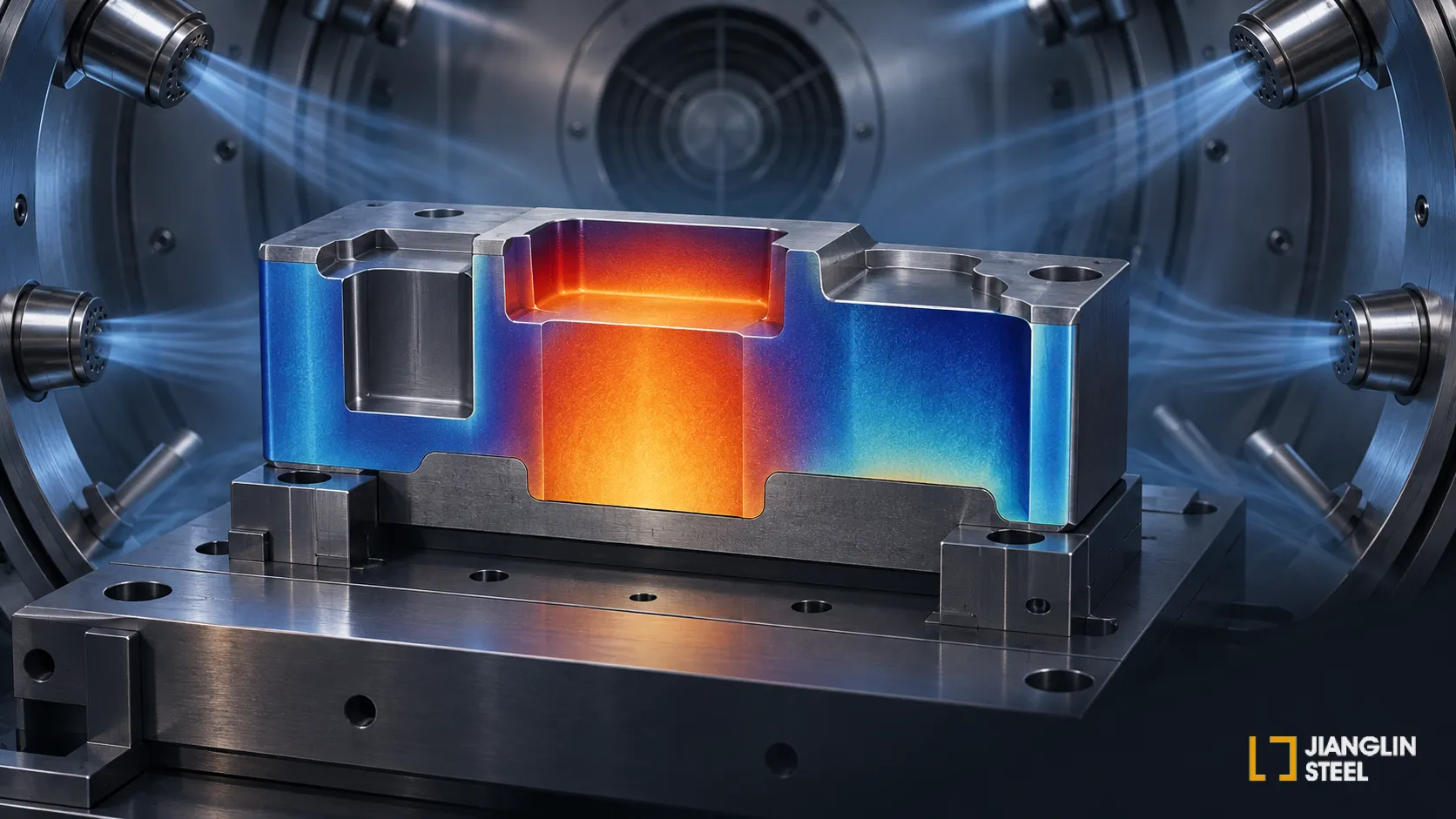
DC53 has good hardenability and can be hardened by air cooling or vacuum-furnace gas cooling under suitable conditions. That reduces the need for a severe liquid quench, but it does not remove cooling risk.
Thin edges cool faster than a heavy center. A blind cavity can restrict gas flow. One face may sit too close to a nozzle while another is shielded by the fixture. The result is uneven contraction and transformation stress.
When only one part in a furnace load cracks, compare its exact position with the others. Check orientation, spacing, gas-flow direction, fixture contact, and nearby heavy components. A nominally correct temperature chart cannot reveal every local cooling difference.
Temper twice and avoid unnecessary delay
Freshly quenched DC53 is hard and highly stressed. It should enter tempering according to the approved procedure once it reaches the specified transfer condition.
Daido publishes two standard tempering ranges: 180–200°C for low-temperature tempering and 500–550°C for high-temperature tempering. Its standard guidance calls for two tempering cycles. The high-temperature route is often selected when dimensional stability, wire-EDM performance, and a useful balance of hardness and toughness are important.
The second temper is not optional repetition. The first cycle changes the hardened structure. Material transformed during the following cooling stage must also be tempered. Skipping that cycle can leave a tool less stable than its surface hardness suggests.
Do not specify only “62 HRC.” Also state the steel grade, target hardness range, critical dimensions, approved treatment route, and any later EDM, grinding, nitriding, or coating operation. For material properties and available forms, see Jianglin’s DC53 steel buying guide.
EDM and grinding can create a late crack
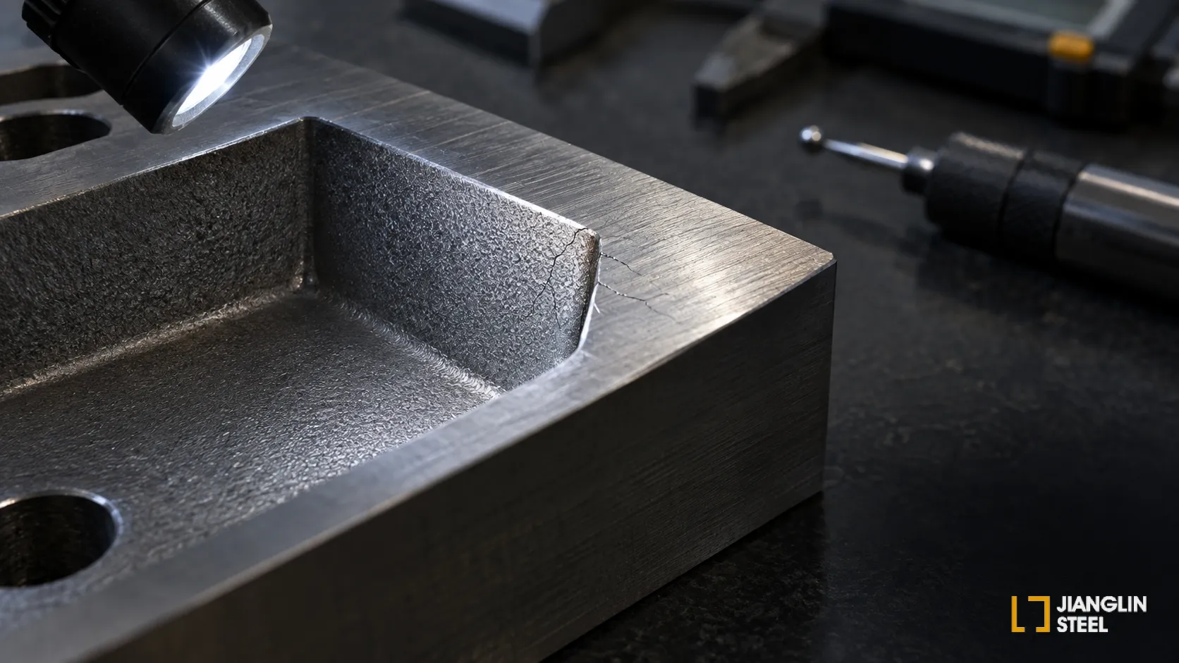
Electrical discharge machining leaves a thin melted and resolidified surface. This recast layer may contain tensile stress and microcracks. Heavy EDM followed by insufficient finishing can leave those defects ready to grow in service.
Use roughing and low-energy finishing passes as a planned sequence. Remove the affected layer where the drawing permits. Critical tools may also require post-EDM stress relief below the previous tempering temperature, using a qualified procedure.
Grinding creates another concentrated heat source. A dull wheel, poor coolant flow, or aggressive feed can produce grinding burn and fine surface checking. If cracks follow the grinding direction, inspect the finishing process before changing the furnace cycle.
Useful checks include surface etching, magnetic-particle inspection where applicable, metallography, and microhardness testing across the affected area.
What should be recorded after a failure?
Do not grind away the crack before documenting it. Photograph the part and mark the crack ends. Record its relationship to corners, machining marks, EDM surfaces, and section changes.
Preserve the steel certificate, furnace chart, load arrangement, tempering record, hardness locations, grinding data, and EDM settings. Fracture origin matters more than the largest visible part of the crack. If the origin sits on an EDM corner, changing the austenitizing temperature may solve nothing.
Frequently asked questions
What is the normal quenching temperature for DC53?
Daido publishes 1020–1040°C as the standard austenitizing range. Holding time and cooling method still depend on effective section thickness, geometry, load, and furnace type.
How many times should DC53 be tempered?
Standard Daido guidance calls for tempering twice, using either the 180–200°C or 500–550°C range according to the required properties and approved process.
Can DC53 crack even when hardness is correct?
Yes. A correct HRC reading cannot reveal every residual stress, EDM microcrack, decarburized layer, or local grinding burn. Hardness is one inspection result, not proof that the entire process was sound.
Is vacuum heat treatment automatically safer?
No. Vacuum treatment controls the atmosphere well, but gas flow, quench pressure, fixture contact, section thickness, and load density still affect cooling uniformity.
Final perspective
DC53 rarely cracks because of one isolated number. Failures usually come from a chain: sharp geometry, uneven machining, rushed heating, nonuniform cooling, delayed tempering, or aggressive finishing.
Break that chain early. Match the cycle to the actual part and treat EDM and grinding as part of its thermal history. For DC53 material, machining, or heat-treatment coordination, contact Jianglin Steel with your drawing, dimensions, target hardness, and working conditions.
Technical references
- Daido Steel: DC53 product page
- Daido Steel: DC53 standard heat-treatment conditions
- Daido Steel: DC53 heat-treatment manual
Process note: These temperatures summarize supplier guidance. They do not replace a qualified specification for a particular part, furnace, section thickness, or target property.
Image note: The three Jianglin Steel-watermarked images are AI-generated technical illustrations. They are not photographs of a Jianglin production facility.